Sections >
User interface circuit
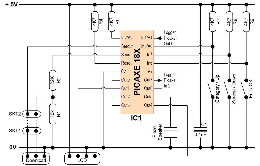
This circuit employs a PICAXE18X chip. This chip has the following interfaces:
• Three button-switches interface into three Input pins. The switches are normally open and are pulled high by 4k7ohm resistors.
• The AXE033 LCD unit interfaces to the PICAXE using the i2C communication protocol. This requires connection to Output1 and Output4, which are the pre-defined pins that perform the i2cSDA and i2cSCL functions for a PICAXE18X chip. An i2c connection has to be used in this project, rather than serial, because the LCD module also houses the Real Time Clock chip, which can only be accessed via i2C.
• Serial communication is achieved with the Data-Logger PICAXE via Input1 and Output7.
• The PICAXE drives a Piezo speaker to sound alerts.
• A standard serial-download circuit is provided, for accepting new program downloads from the PC. To reduce board complexity, Molex sockets SKT1 and SKT2 are used with jumper wires so that the download can be directed to the desired PICAXE chip from the same download socket.
Sections >
Designed using CollectAny software www.CollectAny.com